") Maxime CASIER
Maxime CASIER Creating a welded profile with SOLIDWORKS

Initial situation
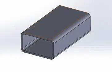
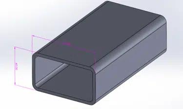
We're going to create a rectangular profile compatible with the welded construction module or the structure system on SOLIDWORKS.
Objective
The aim is to create several sizes of the rectangular tube and store it in a library.
How to proceed
Open a blank Part file
Select Face plane -> Open sketch and create profile (add corner fillets).
The origin will be the profile insertion point...
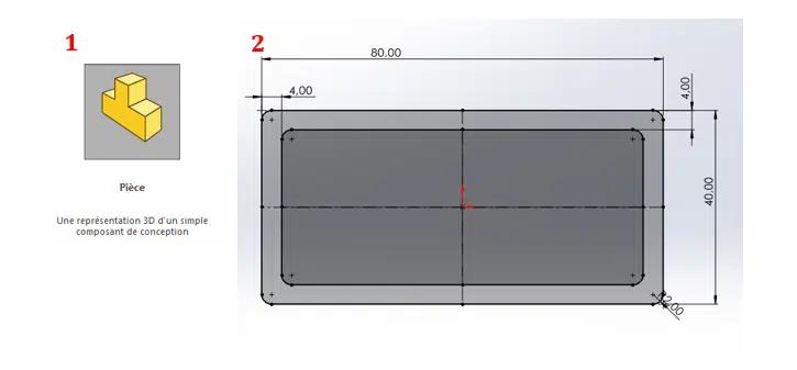
Use the "Point" sketching tool to add points where the profile might later be hooked in.
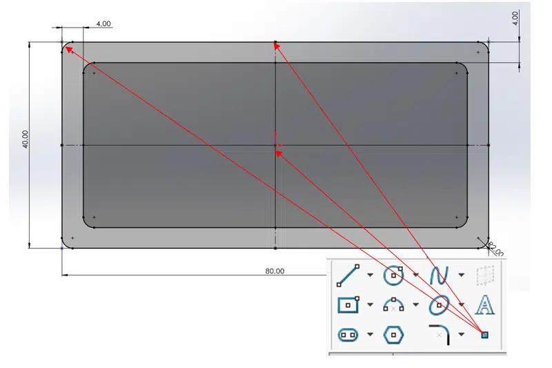
Tip Add a maximum number of points (with clearance if necessary) to provide a wide range of profile orientation options during design.
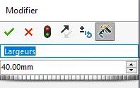
Rename dimensions as "Widths" and "Lengths".
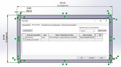
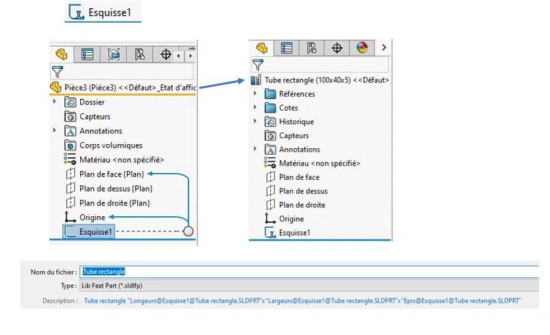
In the document properties, enter a description linked to the dimensions (in the "Value/expression" box, type your text, then point with the mouse at the dimensions).
Example here: Type "Rectangular tube" -> select length dimension -> type "x" -> select width dimension -> type "x" -> select thickness dimension
Then validate the window and validate the sketch. Display the dimensions by right-clicking on the annotation folder in the creation tree, then right-clicking on one of the dimensions to be configured:
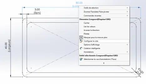
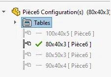
A window opens with a table. Double-click on each dimension to be modified, then enter the different profile sizes:
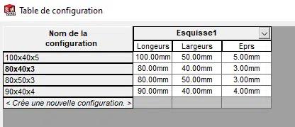
Click on apply and close the table, all your configurations are now created.
Select sketch1 in the design tree, then save in .sldlfp format (save the profile in your profile folder). A small "L" should appear next to the sketch if the action has been successful:
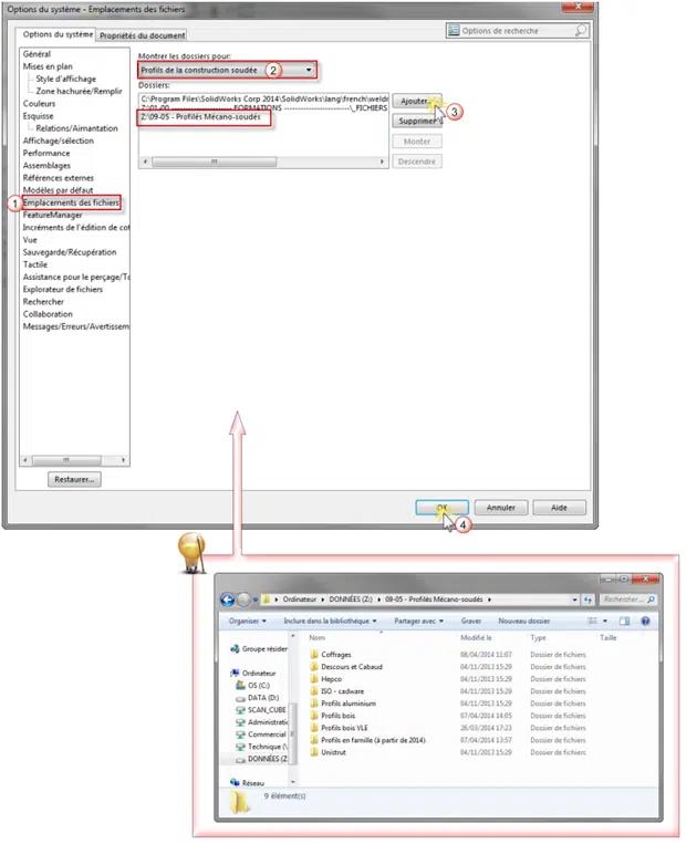
Specify library folder path in options if not already done