") Maxime CASIER
Maxime CASIER 6 essential SOLIDWORKS shortcuts and tips

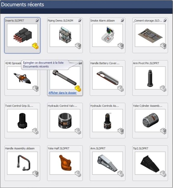
Use recent documents
By pressing the R key in your SOLIDWORKS software, you can access the mosaic of recent files. You can also pin files to this window for permanent access to your favorite files.
You can display up to 16 documents in the "Recent documents" window:
Order search
Since version SW2012, you can search for commands in the SOLIDWORKS search bar. For example, if you're looking for the function "Intersection curve", enter "Curve" in the search field and SOLIDWORKS will list all commands containing this word.
By clicking on the glasses to the right of the command, an animation will allow you to locate the feature in the interface. This command search function can also be accessed via the M shortcut.
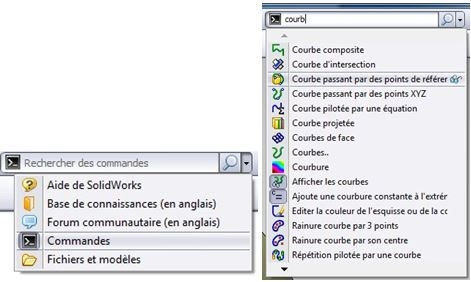
The SOLIDWORKS search bar also lets you quickly search for a function in SOLIDWORKS Help, the knowledge base, forums, or on your workstation.
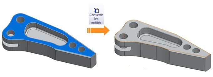
Select external and internal loops
In a sketch, to be able to reuse existing geometry, entity conversion is very often used. As you may already know, when you select a face before launching entity conversion, SOLIDWORKS will automatically convert the outer loop. As you may already know, when you select a face before launching entity conversion, SOLIDWORKS will automatically convert the outer loop.
To convert the inner loop, you'll need to select the face and an inner edge (by pressing the CTRL key). This will allow SOLIDWORKS to select the inner loop instead of the outer loop.
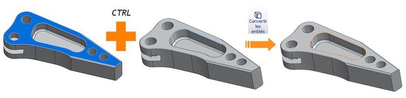
This type of selection also makes it easier to modify your model, as you select the inner loop of the face rather than the edges that make it up. If you later decide to modify the sketch used to create this inner loop (by adding a fillet or chamfer, for example), SOLIDWORKS will reconstruct the model without error.
If you select all the edges by hand, your model will be in error, as it will be missing the fillet edges.
Managing and customizing shortcuts
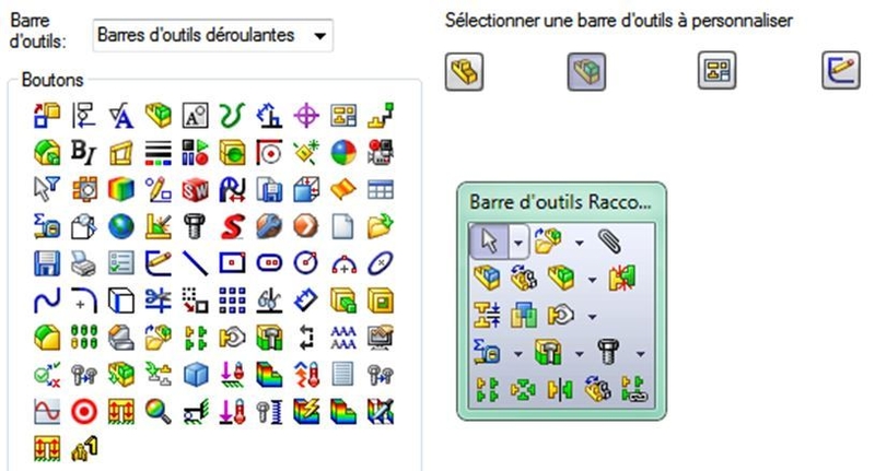
Below the S key on your keyboard is the SOLIDWORKS shortcut bar. This bar adapts to the context you're in (part, assembly, drawing, sketch). It is, of course, fully customizable in all 4 environments. To do this, press the S key to bring up the menu, then right-click inside > Customize.
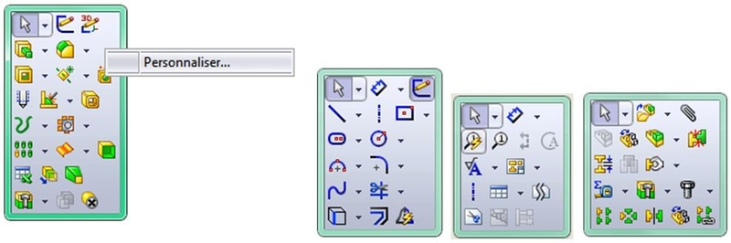
Example menu in the context of a part, sketch, drawing and assembly
To customize, drag function icons into the menu. To delete a function, drag it out of the bar.
Digital input in sketches
To save time when dimensioning sketches, you can activate an option that will allow you to automatically create dimensions while you are drawing.
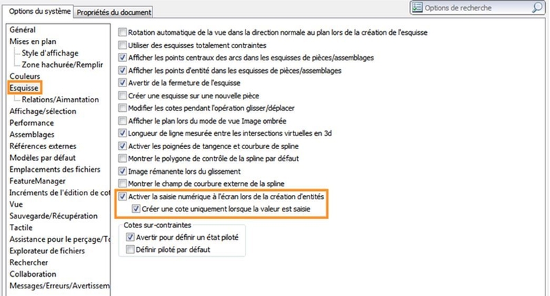
To do this, go to SOLIDWORKS options (Tools > Options), then to Sketch and check the "Enable on-screen numerical input when creating entities" box.
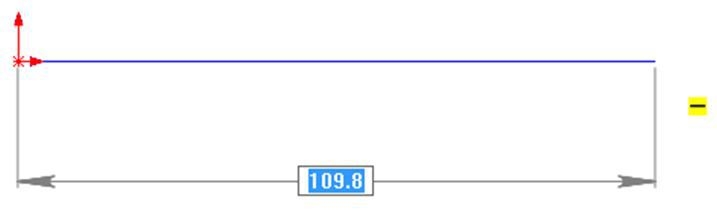
When you draw a line in a sketch, SOLIDWORKS will automatically create its length dimension.
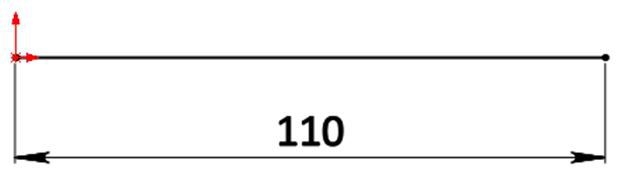
Before clicking to define the end point of your line, you can directly type its length on your numeric keypad to draw a line of the desired length. A length dimension is then created.
If you don't enter anything and choose to place the end point yourself, the dimension value will be set automatically.
To avoid creating a dimension when you don't know its value, you can check the "create dimension only when value is entered" box. In this case, if you don't enter a value when creating the entity, no dimension is created.
Copy with constraints
When you need to insert several identical components into a SOLIDWORKS assembly, it may be useful to use the "Copy with constraints" function. While copying your part, this function allows you to copy its constraints and redefine them.
Let's take an example:
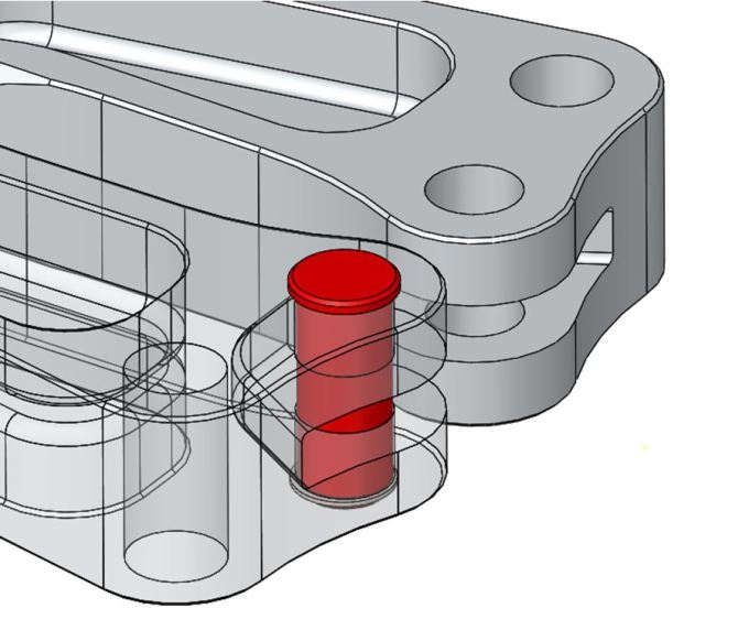
The pin in red has already been inserted and constrained in the assembly.
It is coaxial with the hole in which it is located, and its flat surface is coincident with the upper face of the arm.
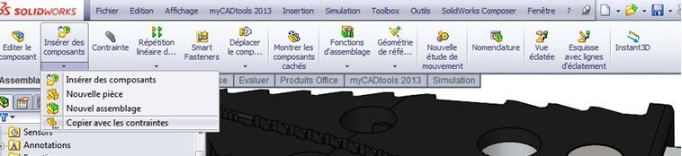
To copy it with these constraints, first select it and then click on Copy with constraints (Assembly toolbar > Insert components > Copy with constraints).
A menu then appears, in which SOLIDWORKS offers you to reuse the same constraints, but also to redefine the parts and faces to which they are referenced. In this way, the new part will be positioned according to a new hole and a new top face. All you have to do is choose which face you want to define the new constraints on.
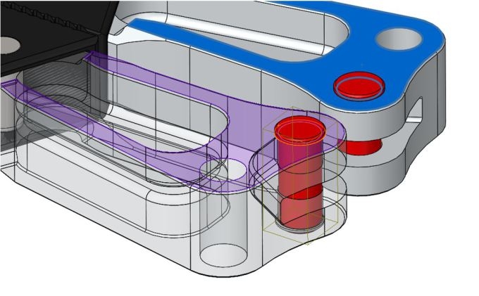
Once the menu has been validated, it opens again, allowing you to insert a large number of parts very quickly.
Do you know any other SOLIDWORKS tips? Don't hesitate to share them on the myCAD forum!