") Coralie
Coralie Developed on SOLIDWORKS surfaces

1. Developed SOLIDWORKS surfaces: the "Flattened surface" function
Thanks to SOLIDWORKS surface unfolding and the "Flattened Surface" function, it's easy to generate decals that can be applied to left-hand surfaces, and even shapes for cutting fabric.
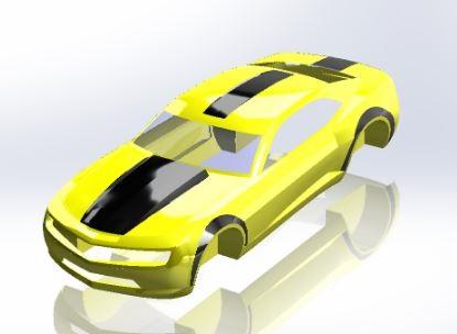
A) Example of flattening a car body
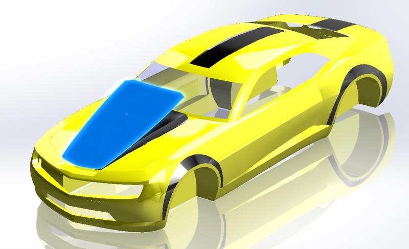
In this example, we'll look at how to generate black decals on a yellow car body.
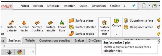
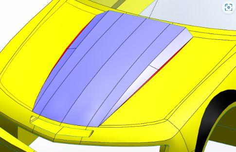
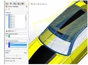
First, select the "Flattened surface" function.
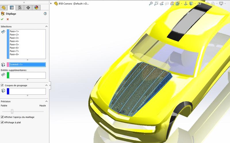
Then select all the faces to be flattened in the first selection field (light blue in the screenshot below).
Also select a vertex belonging to one of the faces to define a fixed point in the 2nd field (pink in the screenshot below).
Finally, confirm. The "Flatten surface" function now creates a flat surface with the desired expanded shape.
2. developed on SOLIDWORKS surfaces: deformation calculation
In addition, flattening allows deformation to be measured in terms of percentage of stretch or compression. In fact, when the flattened film or fabric has to fit a left-hand shape, a compression and/or stretching tolerance must be respected to avoid bad folds.A) Example :
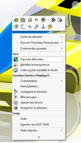
Right-click on the resulting surface.
Click on "Draw deformation".
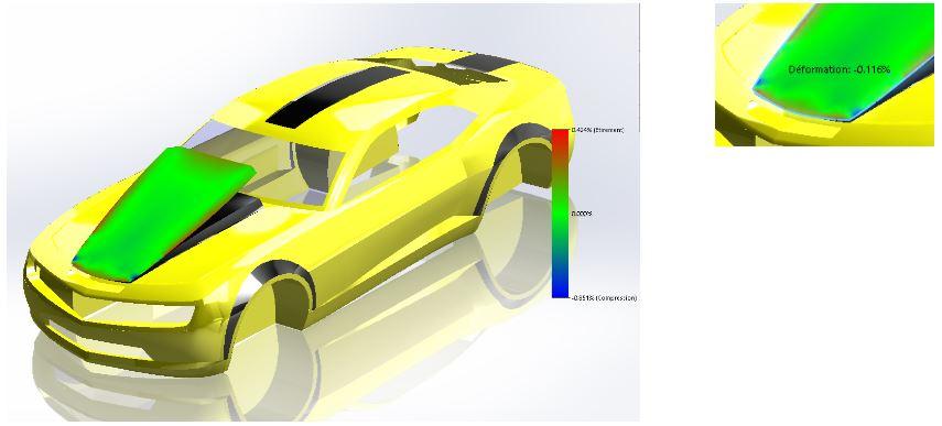
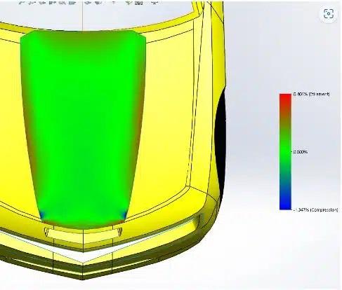
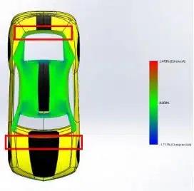
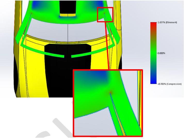
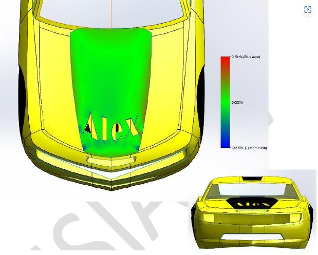
A visual display then appears, with a colored legend showing the areas of compression and stretching on the surface.
The legend can be used to evaluate the maximum compression and stretch. These values can be used to determine whether the development is acceptable, by comparison with the compression and stretch limits of the chosen materials.
Finally, place the cursor on the trace - without clicking - to read a stretch or compression value at the indicated point. In this way, the value is displayed right next to the cursor.
3. SOLIDWORKS surface development: Interpreting the result
A) Reading the result
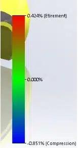
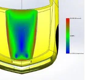
Note that stretch is displayed in positive and compression in negative.
In the example below, the legend indicates a maximum stretch of 0.424% and a maximum compression of -0.851%.
This means that to obtain the flattened result, the reddest areas had to be stretched by 0.424% and the bluest areas compressed by 0.851%.
In reality, if we cut a film flat and apply it to a left-hand surface, we need to reverse the result. The stretched areas will become the compressed areas of the film, and vice versa.
It's a good idea to test the cut materials to determine their tolerance:
An adhesive plastic deco film will have good resistance to stretching, but will not stand up well to compression without generating wrinkles.
Glass fabric is much more tolerant of compression.
B) Result convergence
To flatten surfaces, you need to create a mesh whose precision can be managed using the precision slider at the bottom of the Property Manager.
However, high precision requires more hardware resources and therefore more time. For this reason, we'll be aiming to generate as coarse a mesh as possible.
So, to maintain a consistent result by decreasing precision, we need to generate several calculations with different accuracies to evaluate the lower limit.
As long as the results converge, it is possible to reduce the precision. Otherwise, the precision must be increased until convergence is achieved.
4. SOLIDWORKS surface development: What to do if the compression ratio or stretch limit is exceeded?
A) Example n°1
Let's take a slightly different situation. In the example above, the small gray and red areas will be developed.
Result
Stretch: 0.404
Compression: -1.347
Enlevons les petites surfaces rouges au départ.
Étirement : 0.224 %
Compression : -0.125 %
En changeant très légèrement la forme du sticker, les contraintes sont réduites de moitié pour l’étirement et divisé par plus de 10 pour la compression.
B) Example n°2
Blue faces will be developed.
ResultsStretch: 2.470% Compression: -1.711% We can see that the stresses are concentrated in the areas framed in red.
In some cases of high stretching, it is possible to select edges to generate a notch, and a well-placed notch can release stretching stresses.
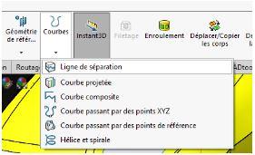
In addition, the "dividing line" function can be used to generate new notching edges as required.
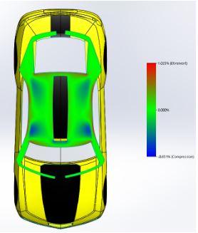
Results
Stretch: 1.025
Compression: -0.851
In this case, the SOLIDWORKS surface development cut-outs made it possible to reduce deformation stresses.
C) Special cases
In some cases, the addition of non-deforming notching can tend to increase the maximum stretch rate in a very localized manner.
This reading is to be interpreted differently: if we were to do as SOLIDWORKS does, i.e. "peel" the surface of the shape to make it flat, it is highly likely that the material would tear at this point. In the case of a sticker cut-out, the shape would be cut flat and then applied to the shape. No tears are to be expected, but rather a fold. What's more, a crease in such a small area won't have as great an impact as the stretch ratio might suggest. On the other hand, an ultra-localized blue zone would indicate the beginning of a tear during installation. It is therefore advisable to interpret certain results without being satisfied with the maximum values calculated.NB: Notch cuts are only possible in stretched zones. Notching in a blue compression zone generates a crossover or superimposition of the development. This makes the notch impossible to cut.
This is why SOLIDWORKS often simply refuses to select the notching edges.
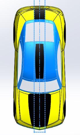
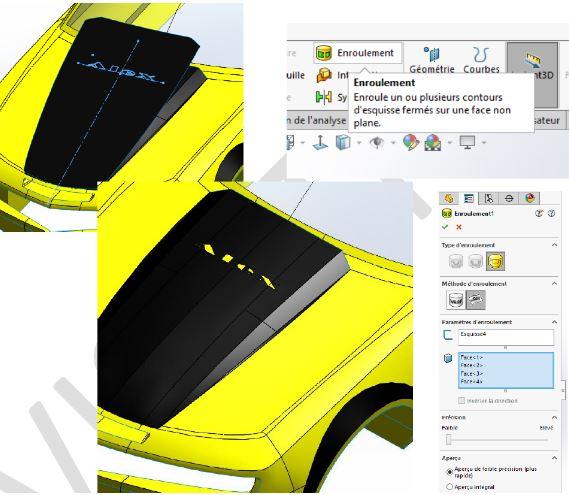
5. SOLIDWORKS surface development tip: Wrap a sketch around a left-hand form
It is possible, within certain limits, to plan the shaping of a sticker on a left surface from a known sketch layout. In a very simple way, it is possible to use these developed faces to generate new sketches that can be rolled up on the starting left surface.
6. Developed for SOLIDWORKS surfaces: Generate a 2D effect from a 3d view from a specific angle
A priori, il est de plus en plus courant de voir la mise en place d’une lecture parfaite (sans déformation) d’un logo ou d’un texte depuis un support en 3D.
Exemple du logo d’un sponsor dessiné sur un terrain de football, basket, rugby… Si nous nous trouvons sur le terrain, le logo apparait complètement déformé. En revanche, il semble parfait aux yeux des téléspectateurs. Cela est rendu possible car la déformation a été prévue pour permettre une lecture parfaite depuis l’angle de vue de la caméra.
Exemple du packaging Un packaging ayant une forme non plane peut faire appel à cette technique pour prévoir une lecture parfaite. Cela évite d’avoir besoin de tourner le produit dans tous les sens.
Pour réaliser cette vue, il faut : A) Prévoir la forme projetée sur le modèle 3D Grâce à la fonction « ligne de séparation » (rubrique 4, exemple n°2), il est possible de projeter une esquisse selon une direction normale au plan d’esquisse.
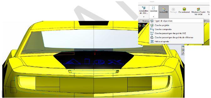
The effect of projection is to offer a distorted image of the original sketch on the support surface. In this way, the sketch pattern will be visible normally and without distortion from a precise viewing angle decided by the designer (in this case, the normal to the front plane). In this case, the surface development function will again distort the pattern to enable flat cutting. Once applied, the sticker will respect the original design, i.e. an undistorted motif when viewed from the front.
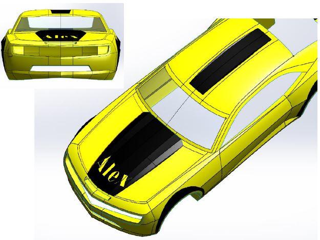
B) Develop the result of the projection
The flat shape obtained is the shape to be cut to obtain the desired result at bottom right.
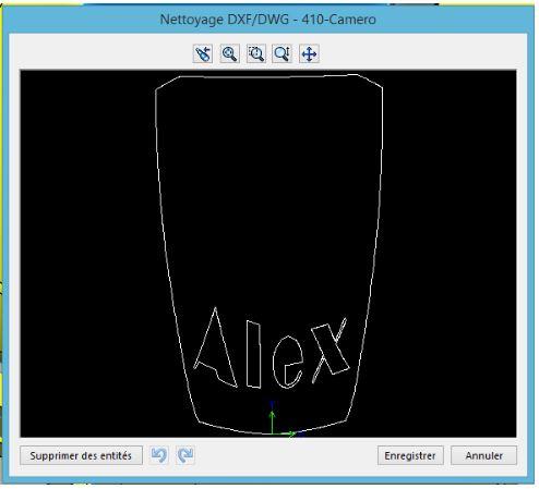
C) Export result for cuttingTo export the result, select the surface and click on File/Save as. Then select the DXF type, click on "Save" and the following Property Manager appears.
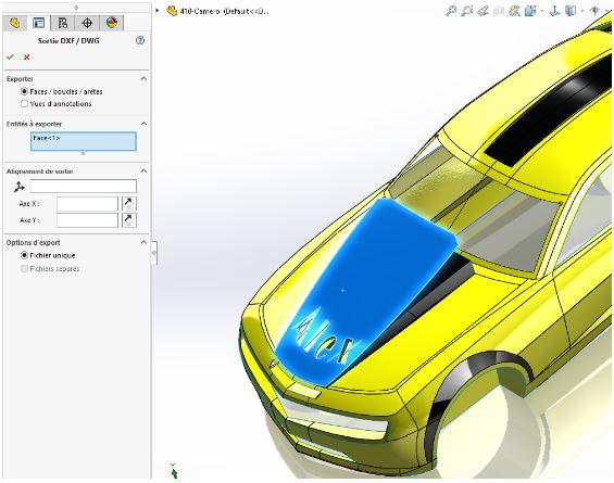
You can then select the "Face/loops/edges" option, then confirm. You can also choose a point of origin and an X and Y axis for the output file. Then click on "Save". The resulting DXF format will be readable by most machines.