") Maxime CASIER
Maxime CASIER Mise en plan SOLIDWORKS

Créer des notes liées aux mises en plan
Objectif
Nous voulons créer des notes à l'aide de propriétés telles que la description, le matériau et la masse dans le modèle 3D et transférer ces informations dans la mise en plan SOLIDWORKS.
L'objectif de ces notes est simple : elles sont mises à jour lorsque les propriétés du modèle 3D sont modifiées, de sorte qu'elles remplissent automatiquement votre cartouche.
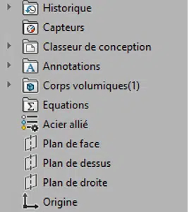
Prenez un modèle 3D avec un volume :
Si ce n’est pas déjà fait, ajoutez un matériau :
Créez les propriétés personnalisées
Plusieurs solutions sont disponibles :
Utiliser SmartProperties de la suite myCADtools
Utiliser les formulaires de propriétés de SOLIDWORKS
Créer les propriétés manuellement
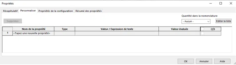
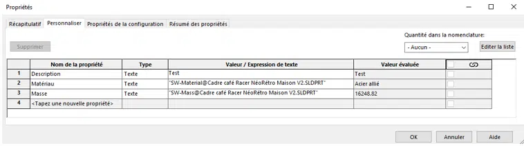
Dans ce tutoriel nous allons créer manuellement les propriétés, pour cela, rendez-vous dans Fichier / Propriétés ou cliquez sur le bouton “Propriétés Personnalisées” Vous arriverez dans ce tableau :
Note : si vous utilisez des configurations, certaines devrons être créer dans l’onglet “propriétés de la configuration”.
Nous allons créer 3 propriétés :
Nom de la propriété => Description_Type => Texte _Valeur /Expression de texte => Test (cette propriété est à renseigner manuellement)
Nom de la propriété
=> Matériau (dispo dans le menu déroulant) _Type=> Texte _Valeur/Expression de texte => propriété SW_Matériau (propriété liée au choix de votre matériau donc automatiquement renseigné)
Nom de la propriété
=> Masse (dispo dans le menu déroulant) _Type => Texte _Valeur/Expression de texte => propriété SW_Masse (propriété liée au volume / matériau donc automatiquement renseigné)
Passons à la mise en plan
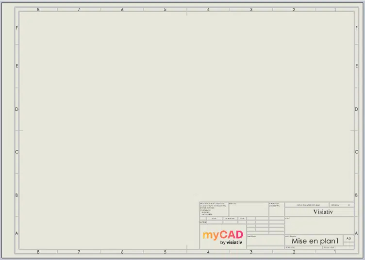
Ce modèle a un cartouche incomplet, les 3 propriétés crées dans le modèle 3D n’ont pas été intégrées.
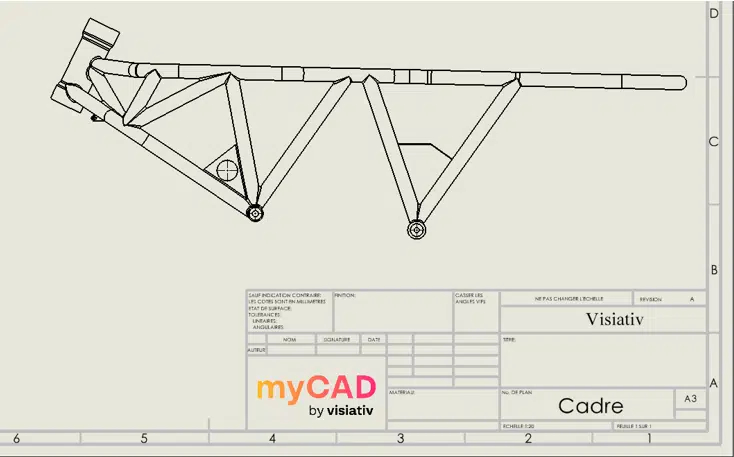
Tout d’abord créez une vue quelconque afin de créer un lien entre les fichiers 3D et 2D, nous obtenons un remplissage partiel des informations du cartouche :
Rendez-vous dans l’onglet “fond de plan” et cliquez sur “éditer le fond de plan“, nous allons maintenant ajouter les 3 propriétés que nous avons crée dans le modèle 3D.
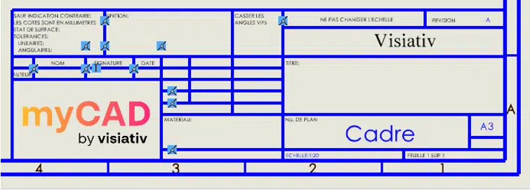
Rendez-vous dans l’onglet “annotation” : et cliquez sur “note” : cliquez pour sélectionner l’endroit où vous souhaitez la créer puis rendez-vous dans le Property Manager.
C’est dans ce menu que nous allons pouvoir créer une propriété liée à une issu du modèle 3D. Cliquez sur le bouton lié à la propriété
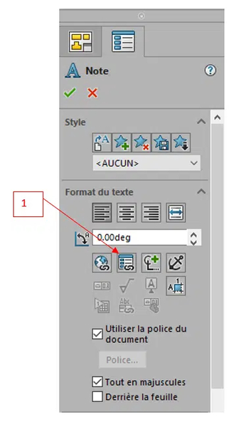
Le menu s'affiche :
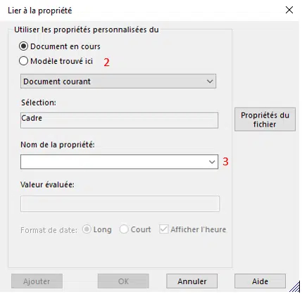
Pour accéder aux propriétés de notre modèle 3D, il sera nécessaire de sélectionner modèle trouvé ici 2 (Modèle 3D) au lieu de document en cours (mise en plan). Une fois fait, rendez-vous dans le menu déroulant nom de la propriété 3 et sélectionnez la propriété souhaitée (ici la propriété description).

Vous pouvez mettre le texte aux dimensions et à la police que vous souhaitez grâce à la barre d’outils mise en forme, une fois la boite de dialogue précédente validée :

Nous obtenons dans le cartouche le résultat suivant :
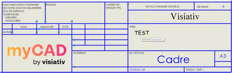
Note : En laissant la souris sur la note vous pouvez voir la syntaxe utilisée par SOLIDWORKS ($PRPSHEET : « Description ») si vous souhaitez créer des propriétés sans vous rendre dans le menu “lié à la propriété”
Il ne vous reste plus qu’a répéter l’opération pour les propriétés suivante :
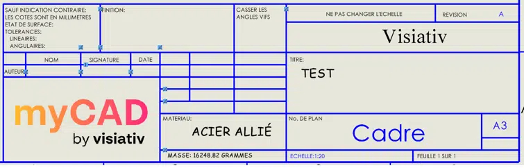
Vous pouvez désormais quitter l’édition du fond de plan.
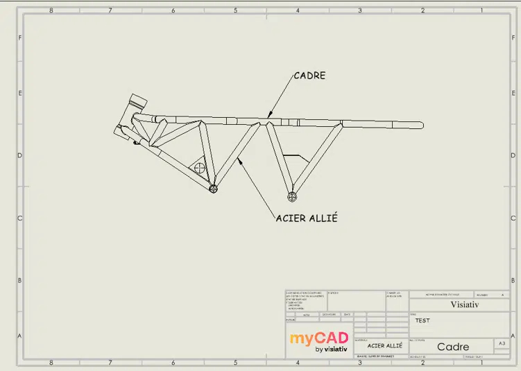
Même si notre exemple ici a été réalisé en insérant des propriétés dans le cartouche, il est tout à fait possible d’effectuer la même opération sur des vues de mise en plan comme dans l’exemple ci-après :
Dupliquer une pièce avec sa mise en plan
L’intérêt est bien entendu que le plan dupliqué référence la nouvelle pièce afin de ne pas avoir à le recréer. Il y a plusieurs méthodes pour dupliquer une pièce et son plan tout en assurant le lien entre le nouveau plan et la nouvelle pièce.
Usage de l’outil SmartProperties de la suite myCADtools
Grâce à l’outil SmartProperties de la suite myCADtools vous allez pouvoir créer simplement, à partir d’un modèle existant, un nouveau modèle avec sa mise en plan associée. En effet, à partir de la modification de valeurs de propriétés, SmartProperties va calculer un nouveau nom et va proposer à l’utilisateur de générer un nouveau document 3D en gérant la duplication de sa ou ses mises en plan associées.
Le lien de référence de la nouvelle mise en plan sera alors modifié automatiquement vers le nouveau modèle 3D.
La méthode du copier/coller
La méthode la plus simple consiste à faire un copier/coller dans l’explorateur Windows. Pour illustrer cette méthode, prenons l’exemple d’une pièce A.SLDPRT et de son plan associé A.SLDDRW :
Tout d’abord, faites un Copier/Coller des fichiers A.SLDPRT et A.SLDDRW dans un nouveau dossier, puis renommez les 2 fichiers copiés en B.SLDPRT et B.SLDDRW.
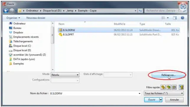
Puis, il suffit d’ouvrir le plan B.SLDDRW avec SOLIDWORKS en lui indiquant qu’il fait maintenant référence à B.SLDPRT au lieu de A.SLDPRT. Pour cela, dans SOLIDWORKS, faire “fichier/ouvrir”, sélectionnez le plan B.SLDDRW et au lieu de cliquer sur “ouvrir”, cliquez sur le bouton “références” :
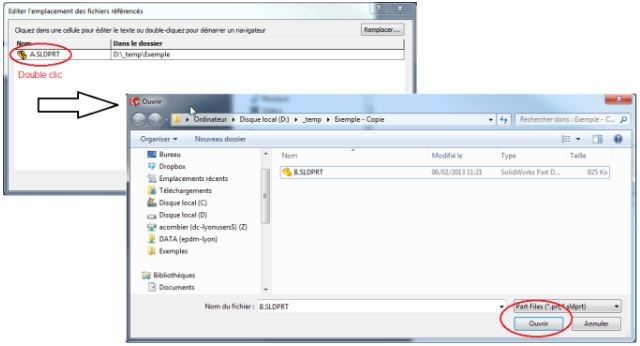
Ensuite, la fenêtre qui s’ouvre vous permet d’éditer l’emplacement des fichiers référencés. Dans notre cas le fichier référencé par B.SLDDRW qui apparaît est A.SLDPRT. Double-cliquez sur A.SLDPRT, et utilisez l’explorateur qui s’affiche pour sélectionner votre nouvelle référence B.SLDPRT, puis validez en cliquant sur “ouvrir” :
Le résultat du remplacement s’affiche alors dans la fenêtre d’édition.
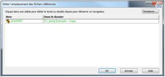
Cliquez sur OK pour valider, puis sur “ouvrir” dans la fenêtre “fichier/ouvrir”. Puis, il faut que vous acceptiez les demandes de mises à jour s’il y a lieu.
Enfin, le plan B.SLDDRW s’ouvre et pointe maintenant sur la pièce B.SLDPRT. Vous pouvez vérifier en faisant “fichier/chercher les références”. Il ne reste plus qu’à sauvegarder le plan.
Créer des coupes de mise en plan directement lors de la conception
Dans les assemblages SOLIDWORKS, il est possible de prévoir ses coupes de mise en plan directement lors de la conception. Nous allons voir comment créer une coupe de mise en plan SOLIDWORKS et une vue en coupe depuis un assemblage 3D.
Vue en coupe dans le 3D
En premier lieu, pour prévoir la coupe de mise en plan, il suffit d’utiliser l’outil “vue en coupe” de SOLIDWORKS en cliquant sur dans la barre de vision Haute. Puis, effectuez les mêmes réglages que pour une coupe 3D.
Toutefois, avant de valider, vous avez la possibilité de sélectionner les pièces que vous ne souhaitez pas couper dans la mise en plan. Comme sur l’image ci-dessous, il suffit d’activer la boite de dialogue “Couper par composant” et sélectionner la ou les pièces que vous ne souhaitez pas couper dans la mise en plan (hors pièces de visserie qui seront générées en automatique).
D’autre part, rien n’est définitif, si vous souhaitez sélectionner les composants à ne pas couper dans la mise en plan un peu plus tard, c’est possible.
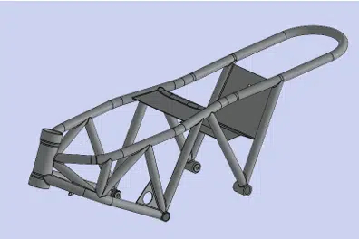
Par exemple, dans l’assemblage ci-dessous, nous avons choisi de ne pas couper l’axe pointé par la flèche rouge.
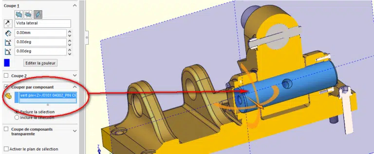
Enfin, pour sauvegarder votre vue en coupe, il ne vous reste plus qu’à cliquer sur le bouton “Enregistrer” en bas du Property Manager.
Options pour la mise en plan SOLIDWORKS
Dans un second temps, après avoir cliqué sur le bouton “enregistrer”, la fenêtre suivante apparaît.
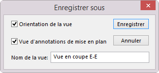
Pour pouvoir récupérer cette coupe dans votre mise en plan, il faut cocher l’option “Vue d’annotations de mise en plan”. Ensuite, cliquez une nouvelle fois sur “enregistrer” pour faire apparaître la deuxième boite de dialogue.
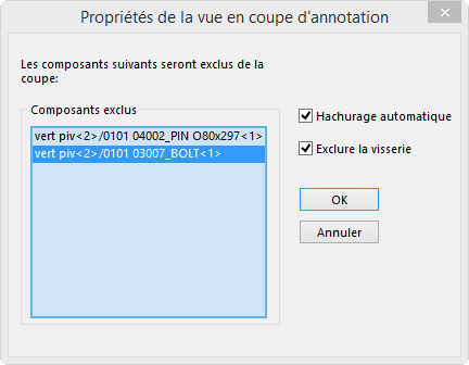
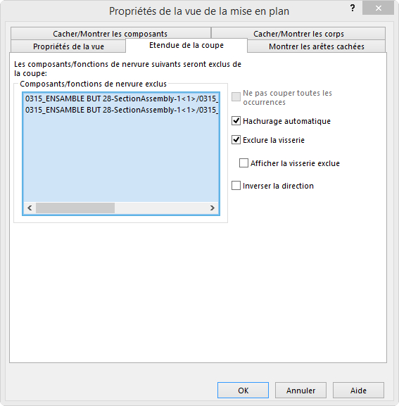
A cette étape, il est encore possible de sélectionner des composants à ne pas couper lors de la réalisation de la coupe de mise en plan. Par ailleurs, vous retrouvez également les options « standard » de mise en plan comme le hachurage automatique et l’exclusion des visseries.
Enfin, cliquez sur “OK” pour terminer
Afficher la vue en coupe dans la mise en plan
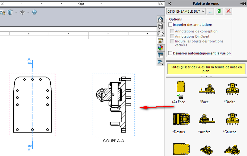
En somme, pour récupérer la coupe définie dans le modèle 3D, il est nécessaire d’utiliser la palette de vue, puis de glisser successivement la vue permettant de créer la coupe suivie de la coupe elle-même. La coupe sera automatiquement représentée en mode « coupé » avec les composants que vous aviez choisi en mode “non coupé”.
D’autre part, vous pouvez évidement modifier les composants à exclure de la coupe de façon traditionnel. Pour cela, il faut faire un clic droit dans la vue coupé “propriété”. Puis, sélectionner les composants à exclure dans l’onglet “étendue de le coupe”.