") Coralie
Coralie Tuto SOLIDWORKS simulation : Comprendre les contacts en simulation statique linéaire en 4 points

Les contacts en simulation statique linéaire permettent de définir les interactions entre les composants lors de vos études sur le logiciel SOLIDWORKS simulation. Etant donné que les outils de simulation ne reprennent pas les contraintes de vos assemblages, il est donc nécessaire de les définir. Notre expert vous explique en 4 points les différents contacts et comment les appliquer dans une étude de simulation.
1. Les différents types de contacts en simulation statique linéaire pour une étude structurelle
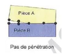
Pas de pénétration Le contact « Pas de pénétration » évite toutes interférences entre les ensembles mais permet un décollement des ensembles. C’est pourquoi il sera nécessaire de bloquer indépendamment les degrés de liberté de chacun des ensembles, puisque ceux-ci peuvent donc glisser l’un sur l’autre et de décoller.
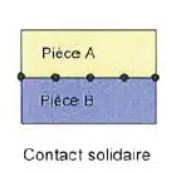
Solidaire « Solidaire » considère les deux corps comme étant liés. Ainsi, aucun décollement ni interférence ne sont possibles, comme si les deux corps n’en formaient plus qu’un.
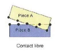
Permettre la pénétration
Ce type de contact permet de définir les deux ensembles comme distincts. Il permet également d’ignorer le contact pouvant ainsi accélérer le calcul. Attention à ne pas utiliser ce contact si les deux ensembles risquent de rentrer en interférence. Il faudra aussi bloquer indépendamment les degrés de liberté de chacun des ensembles.
Ajustement serré Il permet de calculer la force de contact/frottement entre deux faces en interférences et de vérifier la résistance ainsi que le déformé des corps. Ce type de contact n’est disponible que dans un contact entre ensembles. C’est pourquoi, pour définir ce type de contact, il nous faut donc préalablement modéliser les deux corps en interférence. Paroi virtuelle « Paroi virtuelle » permet de créer un contact entre une face et un plan. Il peut ainsi simuler la présence d’un corps ou d’un sol non présent dans l’étude. Ce type de contact n’est disponible que dans un contact entre ensembles et ralenti la simulation. Ce contact est indispensable afin de définir des boulons d’ancrage. Attention, cet élément se crée dans la rubrique « Connexions » mais apparaitra par la suite sous déplacement imposé.
2. La hiérarchie des contacts et l’application des contacts
Contact global Le contact global défini le type de contact par défaut pour toutes les faces en contact entre différents composants au début de l’étude. Il s’agit d’un contact entre composants où la case globale a été cochée. Par défaut, lors de la création d’une étude comportant plusieurs corps traités en maillage volumique ou coque, ce contact est généré et réglé sur « solidaire ». Il ne peut exister qu’un seul contact global dans une étude. Enfin, dans le cas d’un contact ponctuel ou linéaire, il sera nécessaire de faire appel à un contact entre ensemble afin que celui-ci soit pris en compte. Pour le modifier :
Clic droit sur le « contact entre composants global »
Modifier la définition
Choisir le type de contact
Valider
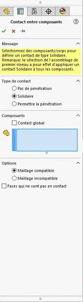
Contact entre composants Le contact entre composants est un contact prenant le dessus sur le contact global si celui-ci est conservé. Il gère le type de contact entre deux composants pour les faces en contact.
Dans le menu « Connexions », cliquer sur « Contact entre composants »
Choisir le type de contact
Sélectionner les composants
Valider
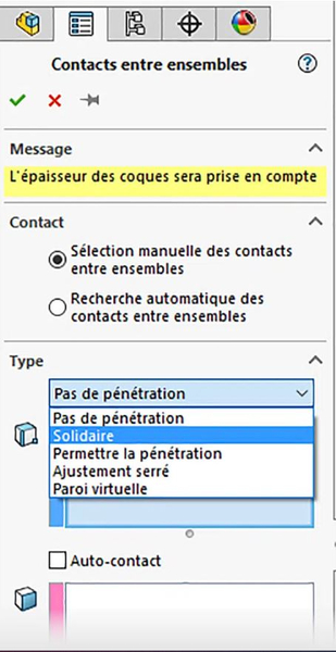
Contact entre ensembles Le contact entre ensembles prend le dessus sur les autres contacts et gère la liaison entre deux éléments (face, arrête, sommet). C’est pourquoi il s’agit d’un contact local permettant de lier des faces en contact ou non. De plus, il s’agit aussi du seul niveau de contact permettant de lier (uniquement en solidaire) le maillage poutre avec un autre type de maillage.
Dans le menu « Connexions », cliquer sur « Contact entre ensembles »
Choisir le type de contact
Sélectionner les éléments
Si besoin, ignorer le jeu entre les faces (contact de type pas de pénétration uniquement)
Si besoin, spécifier le coefficient de friction
Valider
3. Gestions des éléments poutres
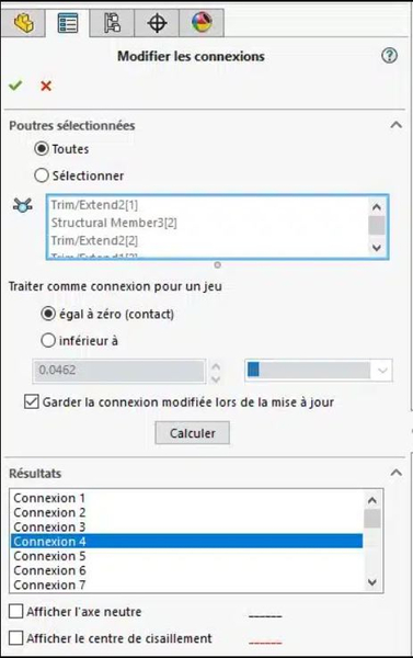
Groupe de connexion Le groupe de connexion est automatiquement défini lors du travail avec des éléments poutres. Il gère la liaison entre ces éléments seulement. Ainsi, il permet de modifier les liaisons entre les éléments poutre, tout en tenant compte ou non d’un jeu. Par défaut, les liaisons sont réglées sur rigide. Pour le modifier :
Clic droit sur le Groupe de connexion
Modifier la définition
Choisir avec ou sans jeu
Calculer
Valider
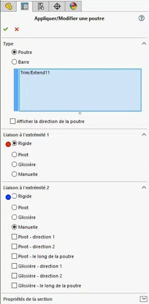
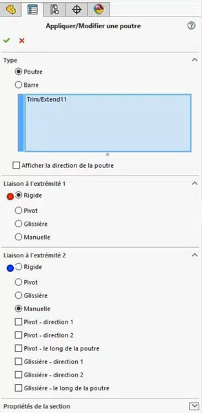
Modification du type de liaisons dans les éléments poutres Afin de modifier la liaison entre deux éléments poutre, il est nécessaire de le faire localement en modifiant la définition de chaque poutre. Pour rappel, comme énoncé précédemment, ce contact est défini par défaut en rigide. Pour le modifier :
Clic droit sur le corps traité en poutre
Modifier la définition
Choisir le type de liaison sur le connecteur correspondant
Valider En manuel, vous pouvez libérer certaines contraintes en cochant la case correspondante. Par exemple, si la case Glissière le long de la poutre est sélectionnée, la force autour de la direction axiale de la poutre a une valeur nulle. Ainsi, l’extrémité peut translater dans cette direction.
Modification du type de liaisons dans les éléments poutres Afin de modifier la liaison entre deux éléments poutre, il est nécessaire de le faire localement en modifiant la définition de chaque poutre. Pour rappel, comme énoncé précédemment, ce contact est défini par défaut en rigide. Pour le modifier :
Clic droit sur le corps traité en poutre
Modifier la définition
Choisir le type de liaison sur le connecteur correspondant
Valider
En manuel, vous pouvez libérer certaines contraintes en cochant la case correspondante. Par exemple, si la case Glissière le long de la poutre est sélectionnée, la force autour de la direction axiale de la poutre a une valeur nulle. Ainsi, l’extrémité peut translater dans cette direction.
4. Vérification des contacts à l’aide du tracé de visualisation des contacts
Le tracé de visualisation des contacts permet d’obtenir un retour visuel sur l’ensemble des contacts définis au niveau d’une étude. Il permet donc de vérifier que l’ensemble des contacts a bien été généré ou pris en compte.
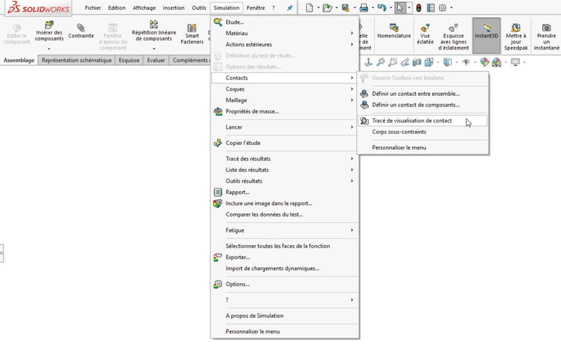
Pour accéder à ce tracé :
Cliquer sur Simulation dans le menu du haut
Cliquer sur Contacts puis sur Tracé de visualisation de contact
Cliquer sur Calculer
Valider quand vous avez terminé l’exploitation du résultat

Conclusion
En somme, nous avons vu que les contacts peuvent être gérés sur différents niveaux hiérarchiques afin de prendre en compte aussi bien le global que le local. La bonne définition des contacts entre vos ensembles représente une part importante de la définition de votre simulation. Cela permet d’éviter un résultat erroné ou encore une instabilité de vos calculs.